Skip to content

Article

Manufacturing a cupboard under a sloped ceiling

Learn how Aleker helps design and prepare custom furniture under stairs, roof slopes and complex sloped spaces.

Illustration for Manufacturing a cupboard under a sloped ceiling

1. Managing an under-slope design efficiently

A cupboard under a roof slope, attic or staircase is rarely standard. The project must follow angles, heights, access constraints and storage needs.

This is exactly the kind of project where a workshop loses time if the design is handled like a standard rectangular cabinet. The slope must be drawn from real site measurements, the references must remain editable, and every part has to stay connected to manufacturing data.

The problem of under-stair or attic furniture

The difficulty is to create useful storage without losing precision. Each side, reinforcement, front and shelf can have a different geometry.

  • Set the slope angle precisely from a digital square or site measurement.
  • Build reference triangles so lengths and diagonals remain coherent.
  • Choose how fillers, doors, drawers and shelves meet the sloped volume.
  • Keep overlaps, clearances and front positions adjustable without manual recalculation.
  • Recalculate uprights, rails, bottoms and shelves when the model changes.
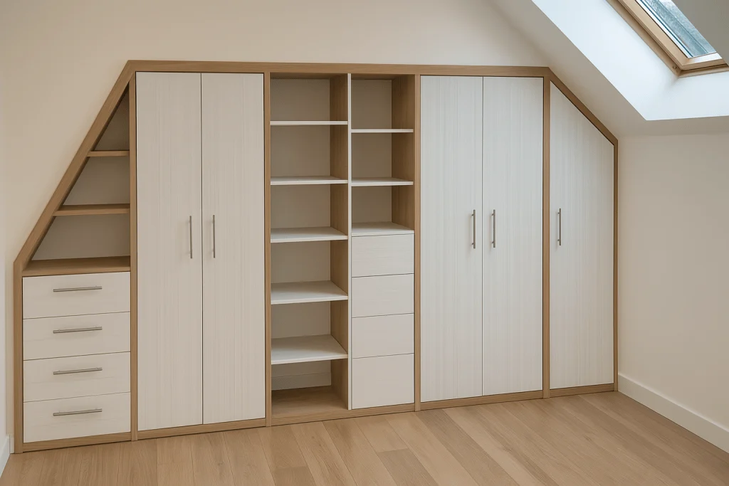
Manufacturing a cupboard under a sloped ceiling: furniture double slope 1

2. From full custom design to quick adaptation
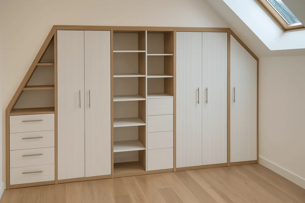
Manufacturing a cupboard under a sloped ceiling: furniture double slope 1

Aleker allows the professional to build a full custom model, then adapt dimensions and elements quickly when the survey or customer request changes.

For a workshop that repeats this type of project, the aim is to create a reliable master model: panel thicknesses, construction rules, hardware choices and clearances are defined once, then adjusted for the next apartment, attic or staircase. The project remains custom, but the method becomes repeatable.

  • Resize a dressing room or storage unit from one site to the next.
  • Reuse a sloped cabinet structure while changing widths, heights and depths.
  • Keep hardware and construction choices consistent across similar projects.
  • Prepare workshop documents without redrawing the complete furniture each time.
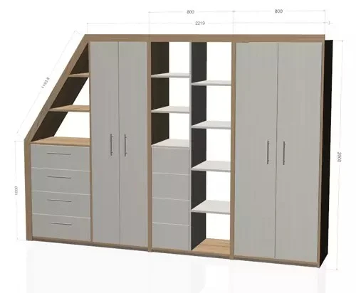
Manufacturing a cupboard under a sloped ceiling: sous pente 1

3. Efficiently handling an under-slope project
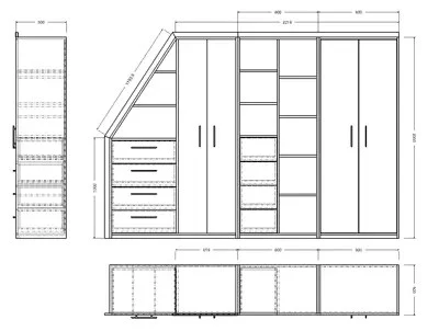
Manufacturing a cupboard under a sloped ceiling: views en drawing sous pente 1

The design must remain clear enough to manufacture. The model helps check the relationship between the slope, cabinet body, fronts and accessories.

A good under-slope workflow separates the steps: first record measurements, then position the main cabinet body, then build the angled references, then add fronts and accessories, and finally generate the manufacturing documents. This avoids mixing presentation decisions with workshop constraints.
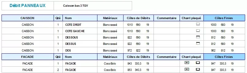
Manufacturing a cupboard under a sloped ceiling: cutting sheet 1

Precise site measurements

Manufacturing a cupboard under a sloped ceiling: manufacturing file 1

A precise survey is essential: heights, depths, angles and available clearance directly affect the furniture.

A laser measure and digital angle finder make the first stage more reliable. Once the values are entered in the project, the slope profile can be reproduced in the drawing and used as a reference for all later dimensions.
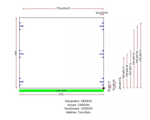
Manufacturing a cupboard under a sloped ceiling: usinage 1

Positioning the cabinet body and reinforcements
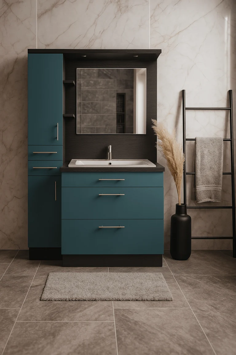
Manufacturing a cupboard under a sloped ceiling: bathroom bleu ocean egger 1 1

The structure must be stable and easy to install, especially when walls, floors or slopes are irregular.

The first vertical upright can be aligned with the slope, then each section can be triangulated to prevent twisted panels and doubtful assemblies. This is what makes the difference between an attractive 3D view and a file the workshop can actually manufacture.

Integrating fronts and accessories

Doors, drawers, shelves and hardware must remain usable despite the slope and limited access.

Hinged doors, sliding doors, drawers and shelves can be positioned while checking clearances and usable access. Manufacturing sheets, machining plans, part lists and exploded views then become the practical output of the same project.

Conclusion

This type of project shows why a flexible woodworking CAD tool is useful: it helps draw the unusual case and still prepare workshop documents.

  • Less time spent redesigning after a new site survey.
  • More reliable manufacturing thanks to angle checks and triangulation.
  • More flexibility for complex under-slope or under-stair projects.
  • Clearer documents for the customer, the workshop and the installer.

Under-slope work

An under-slope cupboard requires precise design before cutting

Under-slope furniture concentrates angles, variable depths, doors, drawers and installation constraints. 3D CAD helps test several solutions before fixing the parts that will be manufactured.

Take useful heights and angles into account from the first design steps.
Check access to storage areas, drawers, hanging rails and open niches.
Generate readable drawings to avoid ambiguity in the workshop.
Adapt manufacturing to real measurements taken on site.
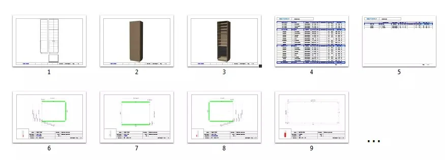
Under-slope cupboard designed in 3D
Plan views for an under-slope furniture project

Custom constraints

Why standard cabinet logic is not enough

The difficulty is not only the sloping ceiling. Every opening, baseboard, wall angle, handle choice and drawer depth can change the project. A flexible design tool lets the workshop preserve freedom while keeping manufacturing data usable.

Atypical shapes can remain editable instead of becoming static geometry.
Customer changes can be tested visually before being sent to production.
Drawings make installation constraints easier to share.
Reusable assemblies help turn a complex project into a future starting point.

Site measurement

A reliable under-slope project starts with the right measurements

Before drawing, the workshop must understand the geometry of the room: height at several points, wall irregularities, floor level, skirting, access, usable depth and the way doors or drawers will open. 3D design then becomes a way to test these constraints before cutting material.

Check the slope line and any difference between theoretical and real measurements.
Keep installation clearances visible during design.
Prepare drawings that separate presentation views from manufacturing details.
Use the validated model as a record when the customer later asks for a variant.

Workshop checklist

How to evaluate this topic in your own workflow

Whatever the project type, the practical question is always the same: can the drawing become useful workshop information without starting again in another file? Use this checklist to connect the article to your own production method, your current documents and the constraints that usually create delays between customer approval and manufacturing.

Choose one recent project that represents your daily constraints, not an idealized demo case, and check how dimensions, materials and customer changes would be handled.
List the outputs you need after validation: customer view, drawing sheet, cut list, cost breakdown, PDF file, optimisation export, CNC data or a complete manufacturing file.
Check which components should become reusable library elements for future projects, including their materials, hardware, names, variables and production properties.
Identify the points where your current workflow requires re-entry, manual checking or duplicated documents, then verify whether a connected CAD workflow removes that friction.
Compare the information needed by each person involved: customer, designer, workshop, installer, subcontractor and machine operator.
Use the demo to test one change late in the project, because revision handling often reveals whether the workflow is genuinely suited to custom work.
Check how the project will be archived after delivery, because reusable references, reliable drawings and clear production data are what make the next similar project faster.
Evaluate the learning curve against the recurring value: a method that saves time on every revision, drawing sheet and cut list matters more than a fast first impression.

Want to see Aleker on your own projects?

A free demo is the fastest way to evaluate the workflow with your real workshop needs.

Request a demo